IEC 61395 Overhead Electrical Conductors- Creep Test Procedures
IEC 61395-1998 Overhead Electrical Conductors- Creep Test Procedures for Stranded Conductors
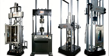
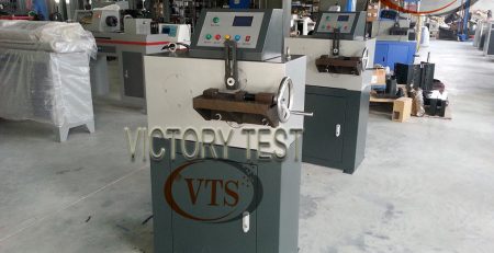
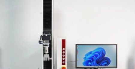
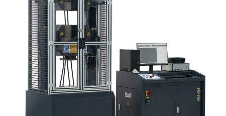
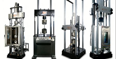
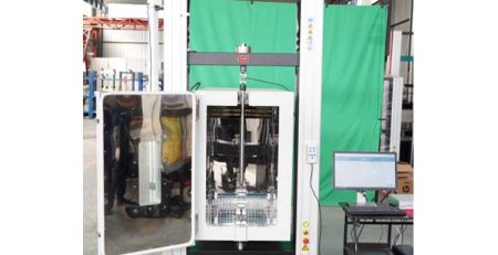
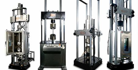
Overhead Electrical Conductors- Creep Test Machine
Overhead Electrical Conductors- Creep Test Machine for Stranded Conductors
1) The IEC 61395 Overhead Electrical Conductors- Creep Test Procedures is a worldwide organization for standardization comprising all national electrotechnical committees (IEC National Committees). The object of the IEC is to promote international co-operation on all questions concerning standardization in the electrical and electronic fields. To this end and in addition to other activities, the IEC publishes International Standards. Their preparation is entrusted to technical committees; any IEC National Committee interested in the subject dealt with may participate in this preparatory work. International, governmental and non-governmental organizations liaising with the IEC also participate in this preparation. The IEC collaborates closely with the International Organization for Standardization (ISO) in accordance with conditions determined by agreement between the two organizations.
2) The formal decisions or agreements of the IEC on technical matters express, as nearly as possible, an international consensus of opinion on the relevant subjects since each technical committee has representation from all interested National Committees.
International Standard IEC 61395 has been prepared by IEC technical committee 7: Overhead electrical conductors.
The text of this standard is based on the following documents:
| FDIS | Report on voting |
| 7/515/FDIS | 7/516/RVD |
Full information on the voting for the approval of this standard can be found in the report on voting indicated in the above table. Annex A is for information only.
OVERHEAD ELECTRICAL CONDUCTORS – CREEP TEST PROCEDURES FOR STRANDED CONDUCTORS
1 Scope
This International Standard is primarily applicable to non-interrupted creep-testing of stranded conductors for overhead lines such as those specified by IEC 61089. Procedures for interpreting the results are also included. The object of the test is principally to calculate creep for any purpose and to compare creep of different conductors. The requirement of this standard aims at an accuracy of 1 %. However, it should be recognized that due to variations occurring in the manufacturing process, the creep obtained in the test is not a precise value for all conductors of the type tested.
2. Normative reference
The following normative document contains provisions which, through reference in this text, constitute provisions of this International Standard. At the time of publication, the edition indicated was valid. All normative documents are subject to revision, and parties to agreements made on this International Standard are encouraged to investigate the possibility of applying the most recent edition of the normative document indicated below. Members of IEC and ISO maintain registers of currently valid International Standards. IEC 61089:1991, Round wire concentric lay overhead electrical stranded conductors
3. Definitions
For the purpose of this International Standard, the following definitions apply.
3.1 sample length
total length of the conductor between the end fittings
3.2 gauge length
distance of the conductor over which the creep is measured
3.3 test temperature
mean temperature taken at the three pre-specified positions along the gauge length or, when more than three measuring positions are used, the mean temperature taken at equal distances along the gauge length.
3.4 test load:
constant load acting on the conductor during the test
NOTE – This causes the permanent time dependent elongation known as creep.
3.5 Loading time:
time required either from preload when preload is applied to test load or from no load to test load
3.6 Duration of test:
time span between reaching test load and the end of the test
3.7 Creep test machine:
complete equipment by means of which the conductor sample is tensioned during the test
3.8 End fitting:
hardware that maintains the electrical and/or the mechanical continuity of the conductor
4. Units, instrumentation and calibration:
Units of the International System of Units (SI-units) shall be used. To ensure traceable accuracy of the test, calibration records of all instruments used in the test shall be kept. The equipment shall be calibrated in accordance with nationally recognized standards. Where no such standards exist, the basis used for calibration shall be documented.
5. Sample selection and preparationIEC 61395 Overhead Electrical Conductors- Creep Test Procedures 5.1 Sample selection The sample shall be taken at least 20 m from the end of the conductor on the drum. It shall be undamaged during removal and preparation. At least three strong hoseclips shall be placed on both ends of the sample to prevent interlayer movement, before it is cut from the drum.
The minimum sample length between the end fittings shall be:
100 × d + 2 × a
where:
100 × d is the minimum gauge length;
d is the conductor diameter;
a is the distance between the end fitting and the gauge length. 1)
The distance, a, shall be at least 25 % of the gauge length or 2 m whichever is the smaller. The total length cut from the conductor shall include the necessary length to provide for the grips at the two ends of the sample. Figure 1 shows a typical set-up.
The sample and the gauge lengths have been chosen with due weight being given to the greater accuracy with which creep tests are conducted in comparison with tensile tests.
Once the sample has been taken from the drum, it shall be kept as straight as possible. If this is impractical the following procedure shall be adopted.
a) Twice the sample length shall be removed from the drum, and the central part shall be used as the sample length.
b) When recoiling for transportation, a coil diameter of 1,5 m minimum shall be used.

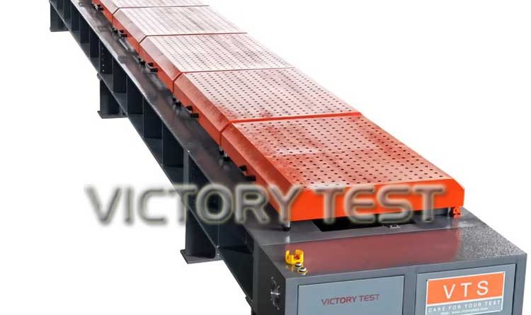
IEC 61395 Overhead Electrical Conductors- Creep Test Machine
5.2 Sample preparation
End fittings, such as low melting point metals and resin bonding etc., attached to test samples shall not allow slippage or interlayer movement.
These end fittings shall be installed when the strands of the conductor are concentric. Where grease is applied to the conductor, the part of the conductor which is held in the grips shall be degreased prior to the installation of the end fittings.
6 Temperature and temperature variations:
The conductor temperature shall be measured in the middle and at both ends of the gauge length, during the test. The measuring devices shall be in good contact with the conductor sample and be insulated against the effects of air movements outside the conductor. If not otherwise specified, the temperature of the test shall be 20 °C.
6.1 Temperature variations:
Conductor temperature variation along the gauge length shall be less than 2,0 °C. Conductor temperature variation during the test shall be less than ±2,0 °C. It is important to ensure that greater deviations than those stated above do not take place. A means of continuously monitoring the air or conductor temperature is recommended.
6.2 Accuracy of temperature measuring devices
The accuracy of the equipment used for temperature measurements shall be within ±0,5 °C. The accuracy of the temperature measuring device used on the gauge length shall be clearly stated in the test report. The method used for temperature control and measurement shall also be fully documented.
6.3 Temperature compensation: Temperature variations shall be compensated, either by using a thermal reference with the same coefficient of thermal expansion as the sample, called reference bars in figure 1, or by using a thermocouple reference. In the latter case, the strain variation is calculated and subtracted from the elongation measurements. Three temperature measuring devices are used, the accuracy of which shall be within 0,5 °C. It shall be clearly understood that the temperature compensation is to reduce the scatter in the measurement arising from the lengt change of the conductor sample due to thermal elongation only. The effect of temperature change on the creep rate cannot be compensated.
7 Load 7.1 Test load The accuracy of the test load shall be within ±1 % or ±120 N whichever is the greater. Load cells shall be used during the test.
7.2 Strain measurement
The accuracy and the set up of the strain measuring device shall be sufficient to determine the conductor sample strain to the nearest 5 × 10⁻⁶. The measuring devices may be of any suitable
type such as micrometer dial gauges, low voltage displacement transducers or optical systems. Uncontrolled rotation during the test, especially of long samples may take place and shall be avoided or compensated for.
8 Test procedure
The sample prepared in accordance with the procedure described in clause 5 shall be placed in the creep test machine. Some machines may require a preload in order to attach the strain
measuring devices. In such cases a preload of up to 2 % of the rated tensile strength of the conductor may be allowed. Prolonged period at preload shall be avoided in order not to
influence the shape of the creep curve. Usually not more than 5 min at preload can be accepted.
The loading time shall be 5 min ± 10 s. The loading should be applied evenly up to the test load, without overload. Where it is necessary to load in steps, incremental steps shall not be greater than 20 % of the test load 2). When step loading is utilised, care should be taken to ensure that the area under the load graph (in a stress versus time diagram) equals that of the
straight line from preload or zero load to the test load. The load shall be kept constant during the duration of the test. 3)
9 Data acquisition
Creep and conductor temperature measurements shall be taken from the moment the full load is applied, i.e. at the end of the 5 min allowed for the loading time. Thereafter, conductor temperature and readings to calculate the creep elongations shall be evenly spaced on the logarithmic time scale 4). The number of these readings shall be at least three in each interval, with ten times increase of the time. The first reading corresponds to zero time and creep. The second reading, which is the first value of the creep, shall be taken not later than 0,02 h after the first reading. When a thermocouple reference is used for the temperature compensation, readings of elongation and temperature shall be made at the same moment. The duration of the test shall be at least 1 000 h, which would predict the long time creep sufficiently accurately.
Most of the creep data available are based on 1 000 h creep tests. Longer times give greater accuracy, but due to the logarithmic presentation, very long times are needed to increase theeffect significantly. It is recognized that due to the unmeasured creep at the beginning of the test, the curvature will result in lower time creep the longer the test continues.
10 Data interpretation
When the conductor elongates according to power law creep, the creep measured for each equal time interval on the logarithmic scale will usually be close to equal, i.e. the creep between 1 h and 10 h is of the same magnitude as that between 100 h and 1 000 h. The regression line which is fitted to the values minimizes the sum of squares of the distances to the straight line. Concentrations of values therefore force the line to pass closer to the centre of the concentrations 5). To make possible an unbiased linear regression to the creep formula, the method requires values to be evenly spaced along the fitted line.

In a graph of elongation versus time plotted on a log-log scale, the measured creep values will form a curve which approaches a straight line for longer times. When the line is fitted to the values, a is the intercept with the creep axis for t = 1 h and b is the slope of the straight line.
A linear regression shall be made using the values between 1 h and 1 000 h to calculate the creep equation. Creep values at less than 1 h are taken for information purposes only.
The constants a and b together with the calculated long time creep for 10 years for purposes of comparison shall be presented in the report, together with nominal agreed temperature and actual temperature variation. A log-log diagram shall be made with elongation versus time up to 100 000 h with the fitted straight line plotted together with the nominal and average temperatures and actual temperature variation. Any further information such as a plot of the creep curve and any additional information shall be agreed upon by the supplier and the purchaser.
Annex A (informative) Practice
IEC 61395 Overhead Electrical Conductors- Creep Test Procedures

A.1 Recommended testing parameters
The following testing parameters are recommended:
– the temperature of the test should be 20 °C;
– the test load should be 20 % of the rated tensile strength of the conductor.
If a complete characterization of the creep behaviour of a conductor is needed, tests should becarried out at least at two different loads and two different temperatures.

A.2 Testing procedure
When long conductor samples are used, the preload will not be sufficient to lift the conductor. In such cases the conductor sample should be supported at regular intervals, either by abalanced weights and lever arms system or by trolleys underneath the sample.

A.3 Sample selection and preparation
The sample preparation aims to prepare a sample for the creep test in which all strands are stressed as equally as possible during the test. Thereby the same tensile conditions are obtained as naturally occur in the very long spans of transmission lines in use. Unnecessary recoiling and bending of the conductor should therefore be avoided.

Moulded end fittings (e.g. resin or low melting metal) are recommended both to reduce the riskof slippage and to avoid disturbing the layers and thereby causing the layers to take stresses unequally.


IEC 61395 Overhead Electrical Conductors- Creep Test Procedures for Stranded Conductors
For the other load capacity, it also can be made according to the customer’s order.
If you are interested in our equipment, please contact:
Contact person: Andy- Victory Test
E-mail: andy@victorytest.com
Mobile & WeChat & Whatsapp: +86-15305307234